Tape Wrapping Wire & Cable Harnesses Guide
This document describes generic methods for applying insulating, thermal or EMI tape materials. It applies to all tape materials which can be helically wound around a wire and cable bundle. The methods described are typical of industry installations and may or may not apply to customer-specific installation requirements. In-house engineering requirements should always be consulted prior to making any production installation. These instructions are provided as an “idea guide” rather than a rigid requirements document. All procedures described herein have been found to provide good mechanical and electrical performance, however, The Zippertubing® Company cannot guarantee end performance results.
Tape users should be aware that a tape wrap jacketing installation is a highly inefficient and costly harnessing solution. Although the tape materials are extremely versatile and appear inexpensive at the buyer level, the finished assembly cost will generally be high because tape wrapping is a very labor-intensive process. Furthermore, tape wrapping is a “craft sensitive” process and the finished installation can vary from installer to installer. Generally, tape wrapping should be limited to short run lengths, cable branch intersections and cable branch legs. To maximize harness assembly efficiency, long run sections of a cable harness should be jacketed using a wrap-around, zip-on jacket material with tape wrap areas kept to a minimum.
Tapes
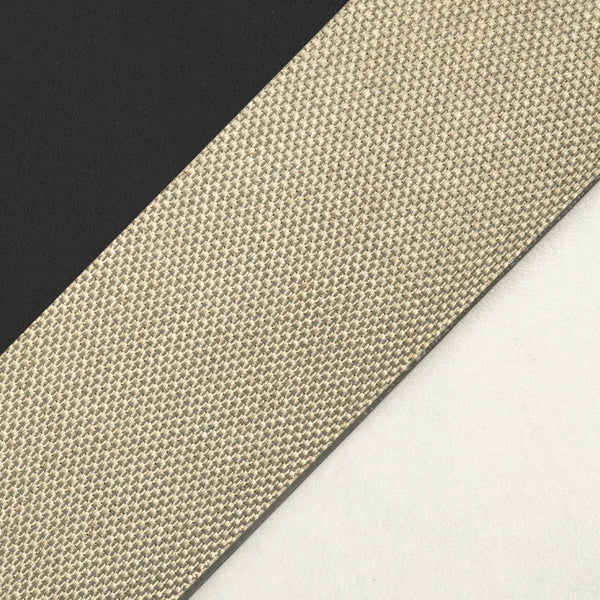
You need to define what type of tape is being used and what the purpose of the tape wrap is. Is the material an adhesive-backed, elastic polymer film, a woven fabric or a metal foil? Is it intended to loosely hold a group of wires together so they all follow the same general direction or is it intended to constrict the wiring into the smallest possible bundle diameter and/or provide a secondary performance characteristic? There are specific tape types which are designed to provide additional performance characteristics to cables such as adding abrasion protection, improving dielectric insulation, providing thermal protection, providing EMI shielding or a combination of these. Knowing the intended use will dictate how much coverage is required, how many layers are required and how precise the installation technique needs to be.
Tape Quantity
The most common question customers ask is “how much tape will I need for my project”? This can be a difficult question to answer since no two installations are the same and some material types are thicker than others. Also, EMI and Thermal materials will require greater coverage to perform correctly. The table below provides a rough approximation of the tape length required to cover one linear foot of cable. The values shown are based on mathematical calculations using a 50% overlap, a straight run of cable and using a tape material thickness of zero. Wrapping a cable that has bends in it will increase the quantity of tape required per foot to maintain the 50% coverage. A good rule of thumb is to add 1/3 of the length/foot to all linear tape length values shown in Table 1. Do not fall into the trap of trying to use a wider tape on a small cable to minimize the footage of tape required. Using too wide a tape for the cable diameter will result in large wrinkles and open gap areas which can defeat the functional purpose of the tape as well as look bad cosmetically. Material widths shown in “Red” are generally considered too wide for use on the corresponding cabled diameter.
Table 1. Tape length per linear foot of cable
| Tape Width (inches) | Tape winds (per foot) | Cable Diameter (inches) | |||||
| /////////// | //////////// | 1/4 | 1/2 | 3/4 | 1.0 | 1-1/4 | 1-1/2 |
| 1/2 | 32 | 25-1/8 | 50-1/4 | 75-3/8 | 100-1/2 | 125-5/8 | 150-3/4 |
| 3/4 | 21-3/8 | 16-3/4 | 33-9/16 | 50-3/8 | 67-1/8 | 84.0 | 100-3/4 |
| 1.0 | 16 | 12-9/16 | 25-1/8 | 37-3/4 | 50-1/4 | 62-3/4 | 75-3/8 |
| 1-1/2 | 10-3/4 | 8-7/16 | 16-7/8 | 25-3/8 | 33-3/4 | 42-1/4 | 50-5/8 |
Installation
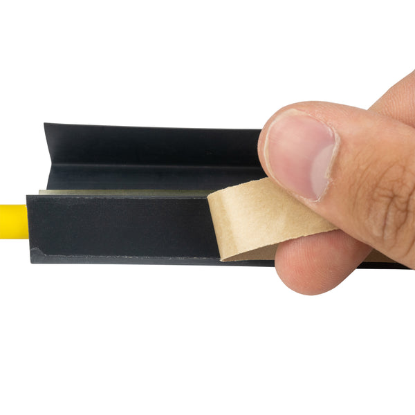
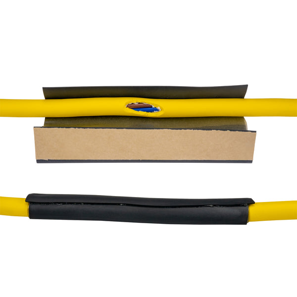
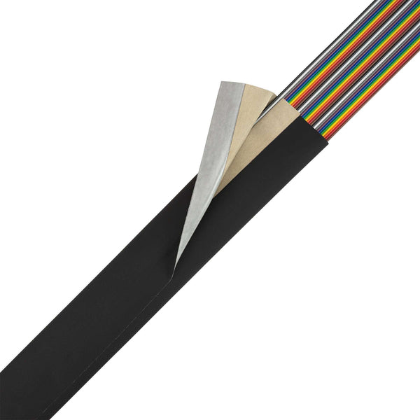
Tape application is a fairly intuitive process, but there are several factors that should be considered before grabbing a roll of tape and beginning. Generally, tapes have an adhesive backing on one side to hold the tape film in place and to help avoid coil slippage once installed. Some tapes have this adhesive exposed as you unwind the roll while others may have a paper release liner that keeps the adhesive from sticking to the material on the roll. There are also tape materials that do not utilize any adhesive at all. Fabric friction tape and self-vulcanizing tapes are just a few examples. With few exceptions, an adhesive backed tape will be installed with the adhesive side facing the cable bundle. If the material has a paper release liner, ensure that you remove it as the tape is being applied around the cables. In most applications, the tape should be wound in helical manner starting the first tape wind at a 75 degree angle (approximate) from the cable run direction. Each wind of tape around the cable circumference should overlap the previous wind by approximately 50% (Figure 1.). Polymer film tapes will have a degree of elasticity (stretch) to them. This will aid in making the tape winds look smooth and uniform and minimize material wrinkles. However, applying an excessive amount of stretch to these kinds of tapes can cause the tape to narrow in width and cause individual coils to pull back and expose part of the sticky adhesive over time. Never overstretch an unreinforced film tape. In contrast, woven fabric or metal foil tapes will have little to no elasticity and with these tapes the starting angle is much more critical to getting the individual tape winds to lay flat and smooth with minimal wrinkling.
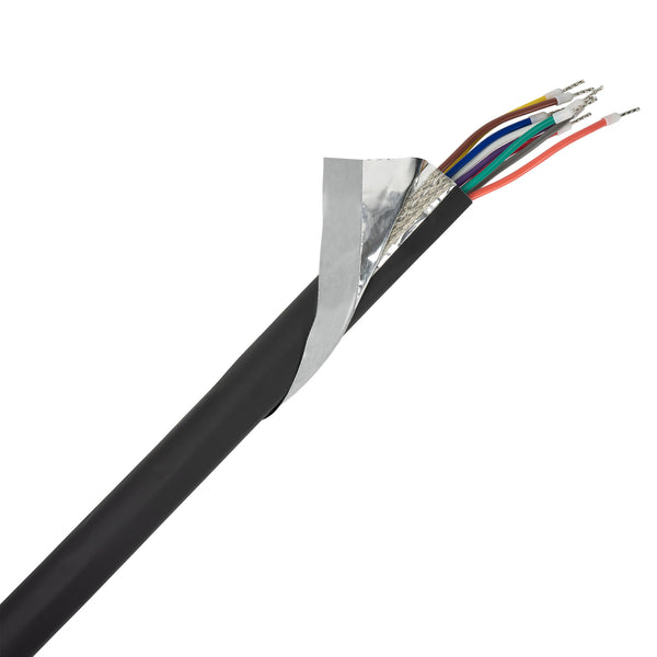
When dealing with multiple breakouts, it may be necessary to back up and wrap the tape over itself to achieve directional changes. In general, you will find it advantageous to start wrapping the smaller breakout legs first using a narrow width tape sized appropriately for the breakout leg diameter. You can terminate this narrow tape wrap several inches down a much larger main cable run. Once all the breakout legs are covered, you may wish to switch to a wider tape to cover the larger main cable run. Experience will dictate when and where these changes make the most sense. When using EMI tapes, ensure that all tape intersections have a 3-4 inch overlap (minimum) and that any materials which have only one conductive side have the conductive sides in contact with one another.
Finally, it is good practice to use a plastic cable tie or fiberglass string tie to retain any tape ends to ensure they do not unravel over time. Never depend solely on the adhesive backing to retain tape ends.


Figure 1. Tape angle and overlap
Grounding EMI Tapes
All EMI shield materials including shielding tapes should be grounded at one end to function properly. There are several ways to achieve a ground pathway when using EMI Tape. The exact method selected will depend on the customer’s EMI shielding performance requirements and the type of material the EMI tape is made from. Always contact your in-house Engineering Department for ground termination requirements before making any grounding termination.
1.) Wrapped Ground Strap
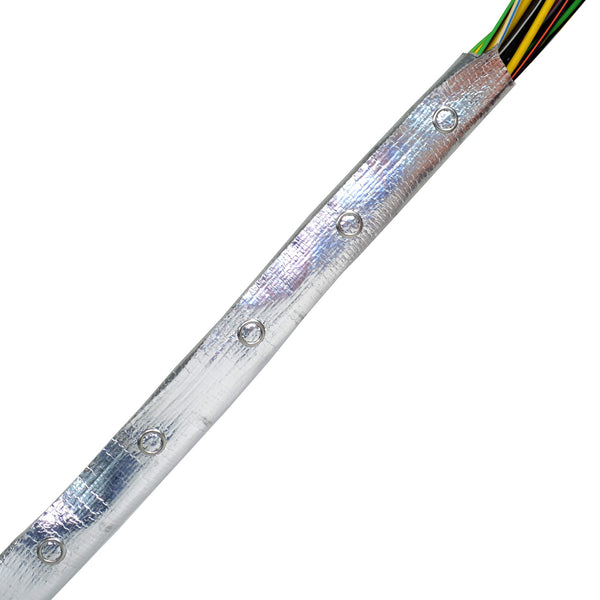
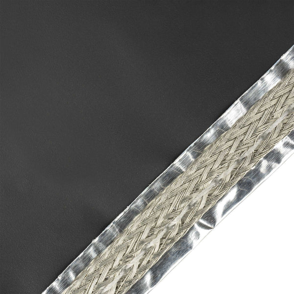
A ground lead (pigtail) can be added by simply helically wrapping a piece of QQ-B-575 tubular braid wire (AWG size as desired) around the cable bundle. Wrap the braid wire coils spaced approximately 1.0 inch apart over a cable distance of approximately 6.0 inches. Then, wrap the conductive side of your EMI tape over these coils. The EMI tape should be wound in the opposite direction than that of the braid wire coils. The helically-wound braid ensures that the bare lead is in contact with the EMI shield material over its entire length and that the lead cannot “nest” into a group of parallel wire leads and lose EMI shield contact. The compressive force of the EMI tape winds ensures that the contact is not lost. The braid wire winding spacing also creates a good tooth interlock of tape in between each braid coil where the tape is tighter on the smaller cable diameter. This approach generates a good ground contact and enough friction that the ground strap cannot be pulled out if accidently tugged. Some customers will choose to extend the braid wire beyond the suggested 6.0 inches, especially on short assembly lengths. (Figure 2)

Figure 2. Ground Strap helically wound around cable.
2.) Soldering and Epoxy Bonding Ground Strap
With some EMI tape materials, like copper foil, it is possible to solder a ground strap directly to the tape. This is not possible with aluminum foil tape and not recommended when using metal plated, non-metallic, fabric-core EMI Tapes. Some metallized-fabric tapes can be soldered too; however, melting of the non-metallic substrate is a common problem. Even a good-looking solder joint to a metallized fabric tape is a marginal joint! The slightest tug on the ground strap will often cause the ground strap solder joint and metal plating on the non-metallic core to separate. Zippertubing® does not recommend soldering to any metallized fabric-material.
It is possible to bond a ground strap to an EMI tape material using silver-or nickel-loaded epoxy. A minimal amount of epoxy should be used and the bare conductor fanned out so as not to create a severe bump which could create an abrasion point on the primary wiring. An extra layer of insulation tape wrapped over the wire bundle in the area directly below any bonded drain lead may be desirable to minimize wire insulation abrasion. The bonded length should be at least 1.0 inch long to ensure a good mechanical bond between the epoxy and shield cloth. Too small of a bond area can result in the conductive shield cloth plating separating from the fabric core if tugged severely.
3.)Connector Termination
There are too many connector and backshell hardware variations to give specific details on how EMI Tape can be terminated to a specific electrical connector type. The following are generic examples that illustrate how an EMI Tape might be terminated to a connector. When terminating to any connector hardware, be sure to confirm the connector body material is electrically conductive and attached to a good chassis ground. Anodized aluminum connector bodies are not conductive. The anodized surface is an electrical insulation. If an anodized connector is to be used, the anodized surface must be removed to achieve a good electrical pathway.
With most connectors there is usually a large step-up from the cable bundle diameter to the connector body diameter. If the connector does not have a backshell that tapers the connector diameter down close to the cable bundle diameter, consider inserting a foam filler directly behind the connector to create a transition ramp. This will allow the tape to transition smoothly from one diameter to the other.
Example #1 illustrates EMI Tape wrapping up over the back of a connector that has an EMI shield compression cone and ring. Ground contact is achieved by having the conductive tape compressed between the cone and compression ring.

Example #2 illustrates a slightly different approach when the connector backshell hardware is a saddle clamp. The shielding tape is simply wrapped up the harness to the area that will make contact with the saddle clamp. Adding several additional tape wind layers in the area where the saddle clamp will compress the cable will ensure good electrical contact and create a compression cushion under the clamp halves.

Example #3 illustrates a small round connector or rectangular connector which has no backshell hardware. This type of termination using a rectangular connector is a very good example of where using the foam transition filler is highly desirable. A banding clamp or mechanical retention mechanism is usually required to ensure that the tape does not slip or squirt back off the connector body. It is generally undesirable to use this type of tape-to-connector termination if the cable/connector assembly is likely to see any movement during operation.

Conclusion
Using tape as a jacketing medium allows the installer a high degree of versatility and creativity to deal with harness transitions, breakouts and termination areas. Both the installer and designer must keep in mind that tape wrapping is not a very cost-effective or time-efficient solution, especially over long run lengths. Because the tape wrapping process is also “craft sensitive” it imparts a great deal of operator variability into the installation. Designers should always specify materials that minimize the degree of installer variability and maximize materials which yield a high degree of repeatability. Doing so will produce the highest degree of overall system reliability. Tape wraps, like all wire harnessing materials, play a vital part in creating a cost-effective and reliable electrical interconnect system. The key point to remember is that there is no one “magic” material that works best for all applications. A reliable and cost-effective wire harness assembly is typically one that maximizes the use of pre-engineered products and minimizes materials that require a large amount of production line operator thinking.