Termination & Splicing of Shielded Products
Introduction

The following procedures describe “generic” methods for splicing and terminating shielded products when applied over electrical cables. The methods described are of typical installations and may not always apply to a customer’s unique installation situation. The goal of this document is to provide the installer with several different termination methods that have been proven to provide a good electrical and mechanical splice.
The methods described are intended to act as an idea guide only and do not reflect all possible methods. Many of the following illustrations depicted in this document show the Zippertubing® with a mechanical zipper type of closure. The procedures described apply to most products, regardless of closure type.
CAUTION: Before attempting any cable repairs or modification, ensure that the power is disconnected, locked out and suitably tagged!
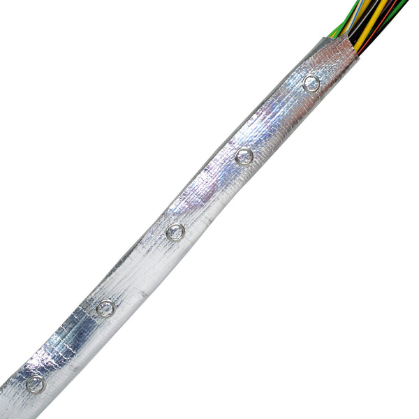
Ground Clamp Preparation - FOIL SHIELDING
Step 1: Cut Zippertubing® jacket 2.0 inches longer than the cable length for each end which will be grounded.

Step 2: If a ground braid is present, pull the stitching from the braid back 2.0 inches from the end of the jacket and then cut off the loose braid. Cut the loose portion of track “A” and along the edge of the track “B” back 2.0 inches each.

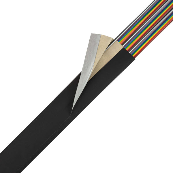
Step 3: Fold 1.0 inches of foil back onto itself and crease firmly.

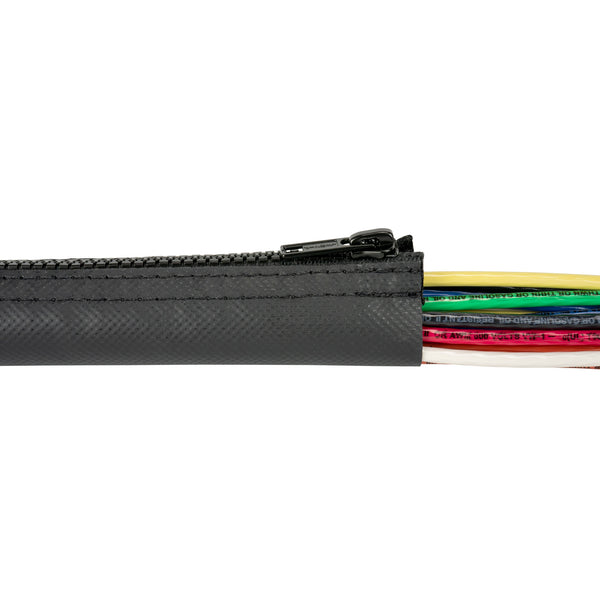
Step 4: Wrap Zippertubing® around cable and zip closed. Attach connector ground clamp hardware over exposed Zippertubing® foil surface.

Shield Splicing
There are several methods of electrically and mechanically joining several pieces of EMI-shielded Zippertubing® together. The following illustrations depict several methods of achieving good electrical and mechanical joints. They vary depending on the end-use application and environmental condition to which they are exposed. These are by no means the only methods possible.
Lap Splicing
This method involves removing the jacket insulation (or folding the jacket inside out; thin materials only) for a distance of several inches from the jacket end and installing the next piece of shielding over the exposed metal shield of the first jacket. The pieces can be held together using plastic or metal cable ties. This technique is generally acceptable in applications where the finished cable assembly is not subject to post assembly movement.

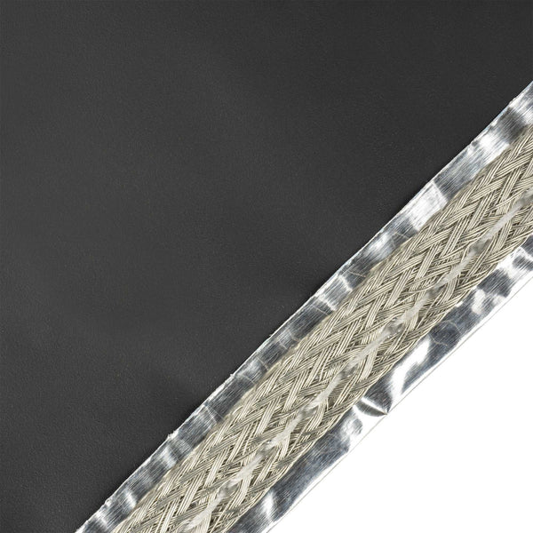
Splice Grounding Braids
This technique is a slight variation of the “Lap-Splice” method described above. It involves removing a small amount of the stitching holding the grounding braid straps to the shielding material, at the ends of the two pieces of Zippertubing® shielding which is to be spliced. Once the braid straps are loose, the two ends can be butt-spliced together, using a standard 14-16 AWG crimp style butt splice. Once the braids have been spliced together, the shields can be “lap-spliced” and mechanically tied.

Soldering Shield Material (SHX2, SHX4 AND ZIPPER-MESH ONLY)
This method applies to the SHX2, SHX4 and Zipper-Mesh® type of shielding materials only. The procedure involves removing one inch of jacketing material from the two ends of the jackets to be spliced, lapping the shield materials over one another (as described on the previous page) and then soldering the shield materials together. The shield material in these products is made from tin-platted, copper-clad, steel-wire mesh and will solder easily using 63/37 tin/lead solder. Use an “RMA” cleaning flux prior to soldering to eliminate any oxidation of the tin-plated surfaces that may have developed since the shield was manufactured. The lap-splice joint may be spot soldered or the entire perimeter may be soldered depending on the degree of mechanical strength the application demands. Keep in mind that soldering will make the joint area rigid. Clean the solder joint with isopropyl alcohol (IPA) or equivalent and allow the solvent to evaporate completely. Wrap the solder joint area and the insulation jacket material back several inches from the solder joint using polyurethane ZT-Tape® adhesive backed electrical tape.


Shield termination
Shield termination to a good ground source is extremely important to over all system performance. The installer should consult any in-house installation drawings, process procedures or the system engineer prior to making any terminations. Some applications may require that only one end of the shield is terminated while others may require both ends to be terminated. Many times it may not be possible to make the “ideal” termination due to hardware variations or a retrofit installation. The following methods are examples of typical termination scenarios and Zippertubing® does not endorse one method over another. All of the termination methods described below have been used with success in the past. However, your specific system requirements may dictate the use of one method versus another.
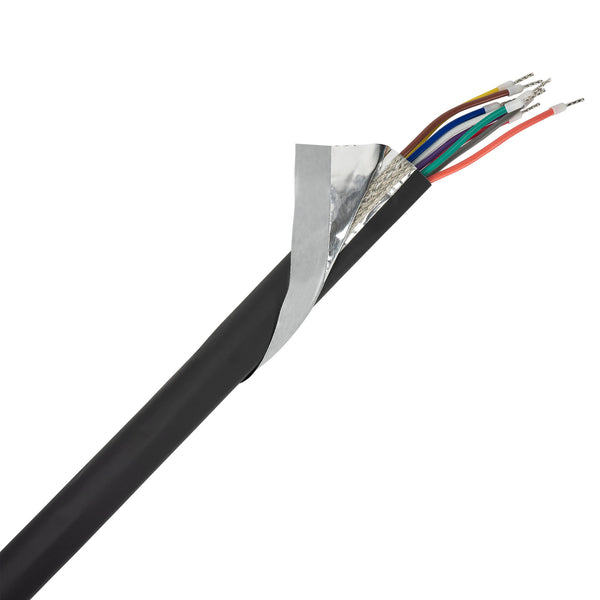
Pigtail Termination
This method involves creating a drain wire extension to reach from the end of the shielding jacket to the intended grounding point. This can be achieved three different ways, depending on the secondary materials available. All three methods create a ground wire pigtail that can be soldered or crimped to terminal hardware for attachment to the grounding surface.
IMPORTANT: To obtain the best overall shielding performance from a Zippertubing® shielded jacket, it is very important to plan the installation so the drain wire (pigtail) length is kept as short as possible.

Option 1. This method involves soldering a grounding lead of the desired length directly to the tin-plated copper braid wire that is sewn into the shield material prior to zipping the jacket on the cable.

Option 2. This method is somewhat similar but requires that approximately one inch of the stitching holding the drain wire braid to the shield material be removed at the end of the shielded jacket. Once the braid wire is loose, it can be mechanically spliced to a secondary wire using a standard 14-16 AWG crimp-style butt-splice.

Option 3. This method assumes that no secondary grounding wire is available. Ensure that you have plenty of extra Zippertubing® shielding material available prior to processing any assembly using this method. Remove the stitching hold in the drain wire braid to the shielding material the same distance required to reach the intended ground plane. Using a pair of scissors or shears, cut the shielding, jacket and zipper closure mechanism back the same distance (do not cut the drain wire braid). Be sure that you have enough of the shielded jacket material length available so that you don’t come up short at the opposite end of the cable!

Connector Body or Chassis Feed-Thru Stub
Shield terminations can also be accomplished using the cable connector body as a ground path if the connector is of an electrically conductive material and is electrically bonded to a chassis ground. This requires that the Zippertubing® shielding material be sized to the largest diameter of the connector body rather than the wire bundle since the connector is usually larger. A metallic, tubular stub feed-thru extending from the chassis wall (similar to a connector) is also an ideal mounting and ground location. By wrapping the Zippertubing® around these components it is possible to achieve a 360-degree EMI seal which can be important, especially at the higher frequency ranges. Metal or plastic banding clamps or tie-wraps can provide the mechanical compression and jacket retention required to hold the jacket in place.

Some military-style connectors have specialty backshell hardware, such as a “saddle clamp” or an EMI “compression ring”, that can also provide a conductive pathway to ground. These features may require that the outer insulation jacket material and closure mechanism be trimmed away to expose the conductive shield material and allow the material to fit into the tight spaces of the connector. Some Zippertubing® shield and jacket combinations are very thin and may be thin enough to be folded back onto themselves to make the electrical contact required by the hardware. The installer will need to determine what approach is best based on the specific connector hardware being used.

Splayed Shield End
This method can be used when cables pass through a bulkhead or enter a box that has no connector or feed-thru hardware available for termination of the shielded Zippertubing jacket. The process requires that the end of the Zippertubing be fanned out or split into two flat tongues to allow placement of the shield material against the bulkhead wall. This approach may require the Zippertubing be sized larger than the cable diameter to provide enough material to cover the bulk of the wall opening and still allow for attachment to the wall. If the jacket is to pass through the hole and make contact with the inside wall, then the insulation jacket may need to be removed or folded back onto itself to ensure that the shield material is in contact with the inside wall. This concept generally does not provide a 360-degree EMI seal but is usually superior to a pigtail grounding wire lead. The box or bulkhead surface must be electrically conductive and the installer shall determine the attachment hardware.

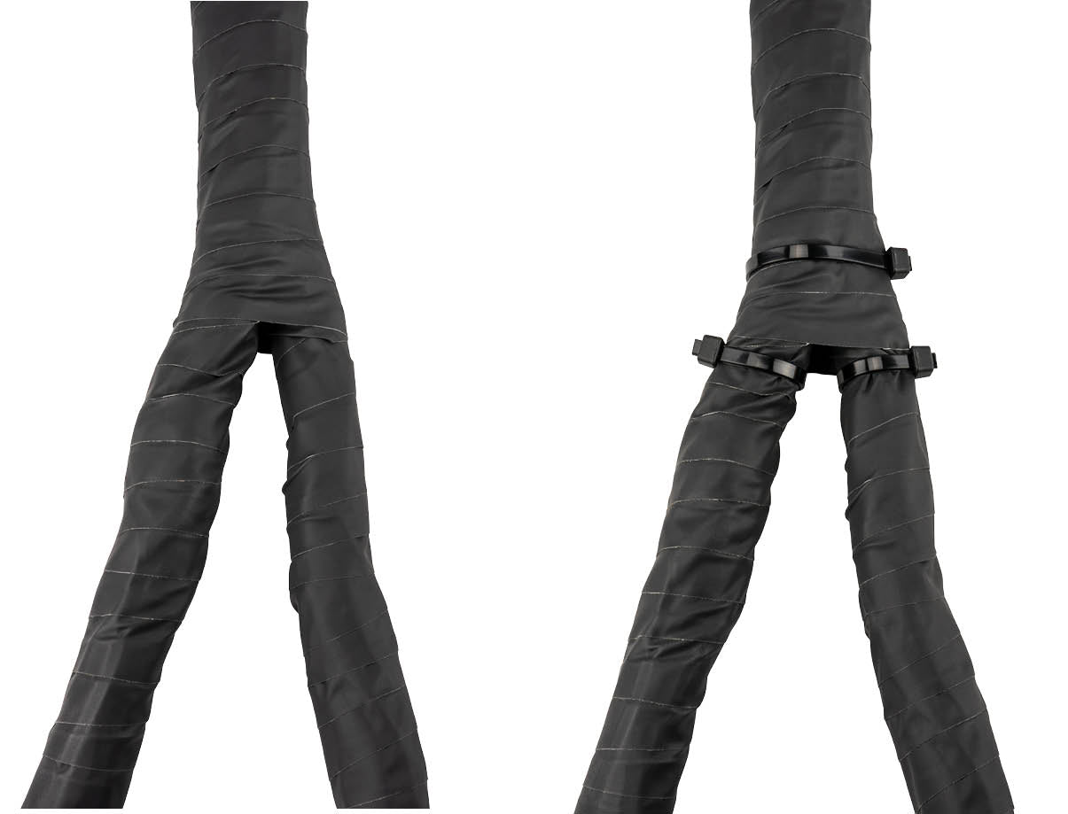
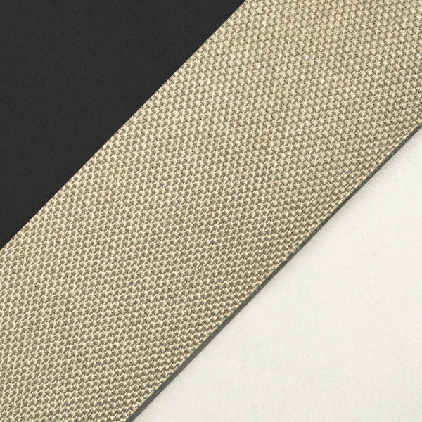
Transitions & breakouts
This process involves wrapping the transition or breakout area of the cable with a conductive shielding tape prior to installing the Zippertubing® shielded jacket. Use one of Zippertubing’s EMI shielding tapes that utilize materials similar to those found within the shielded Zippertubing® jacket you intend to use. For Aluminum foil and knitted wire-mesh shielded jackets, use Zippertubing’s “Zip-Mesh-Al” tape. For products utilizing metallized shielding fabric or “Z-3250-CN” shielding tape, contact Zippertubing® directly for the correct materials and product part numbers.

Spirally wrap the wire bundle in the breakout area using the appropriate EMI shielding tape. Use a 50% overlap technique and cover each leg of the breakout 3 to 6 inches (exact dimension will vary with cable diameter) from the breakout fork. Ensure that the fork area is fully covered.
Install the individual pieces of Zippertubing® shielded jacket material over each leg of the tape-wrapped harness. You may wish to splice the ground braid wires (if applicable) from each leg of the shielded jackets together as previously described. Position all pieces as close to the fork area as possible.

Use Zippertubing’s “ZT-Tape®” polyurethane insulating tape and over-wrap all legs of the breakout. Use a 50% overlap technique and ensure that the fork area is completely covered. Install string ties, cable ties or banding clamps to each leg of the taped assembly to ensure good shield-to-shield contact and stop any shifting of the assembly.