How to install Shrink-N-Shield
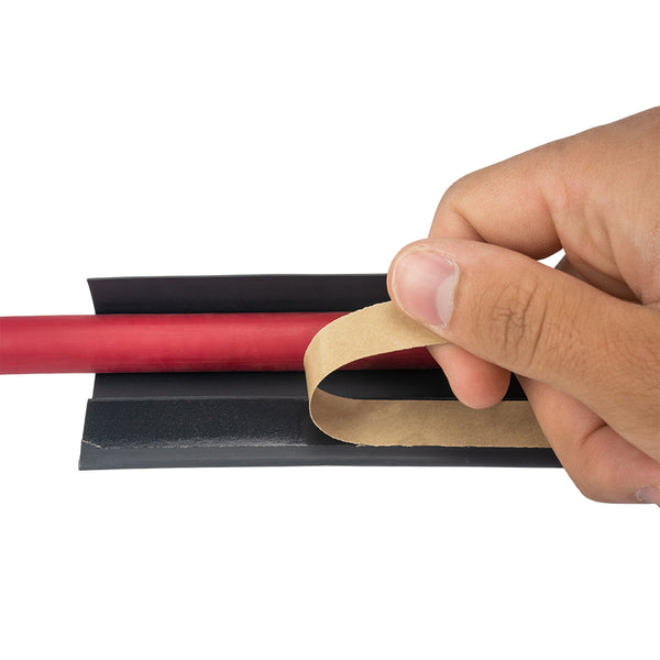
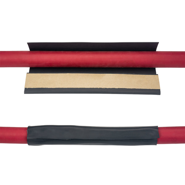
Shrinking
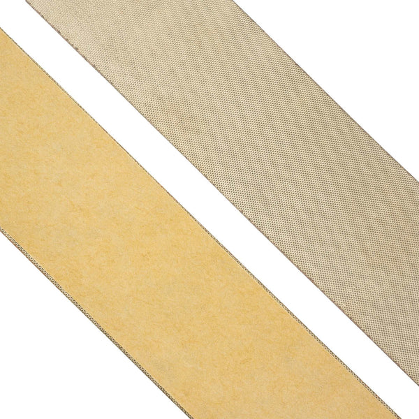
When installing Shrink-N-Shield® tubing, use a tube reflector on the heat gun nozzle wherever possible. If a reflector is not used, the tubing recovery will not be uniform and the installed tubing may have thin spots.
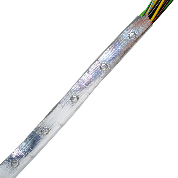
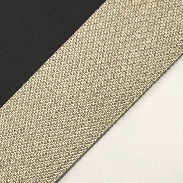
Shrink-N-Shield® tubing will begin shrinking at temperatures above 90°C. A heat gun with a temperature setting of between 120-140°C is sufficient to shrink the tubing and yield good installation results. Since the EMI shield cloth inside the tubing does not shrink, but rather folds up, be aware that the tubing surface may show visible wrinkle lines and will not be as smooth as normal heat shrinkable tubing. Application of excessive heat in an attempt to remove these wrinkles may blister the shrink tubing surface and/or damage the EMI shield cloth inside. Surface wrinkles mirroring through the shrunk tubing from the shield underneath are normal when installing standard (2:1) and thin wall versions of Shrink-N-Shield®. Mirroring of shield wrinkles will be less pronounced when using (3:1) and (4:1) shrink ratio tubing’s since the wall thickness will be greater.

Shield Grounding
All EMI shield materials should be grounded at one end to function properly. There are a variety of ways to achieve a ground pathway when using Shrink-N-Shield® tubing. The exact method selected will depend on the customer’s EMI shielding performance requirements. Always contact your in-house Engineering Department for ground termination requirements.
A: Wrapped Drain Wire
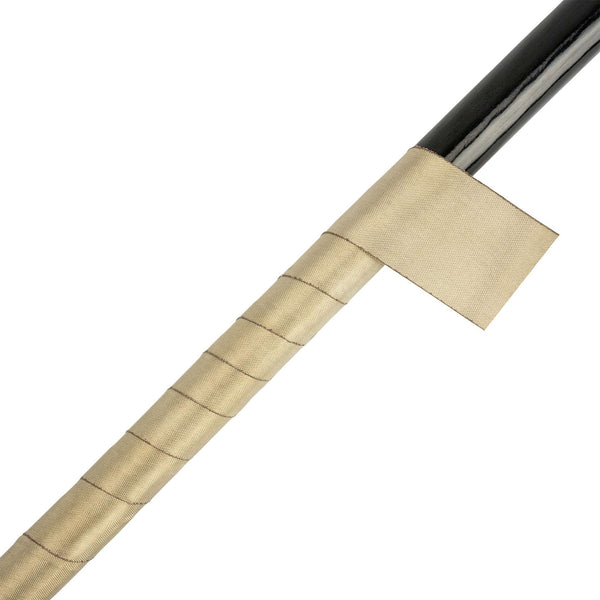
A ground lead (pigtail) can be added by simply helically wrapping a piece of QQ-B-575 tubular braid wire (AWG size as desired) around the cable bundle with the braid wire coils spaced approximately 1.0 inch apart over a cable distance of approximately 6.0 inches and then shrinking the Shrink-N-Shield® tubing over the coils. The helically wound braid ensures that the bare lead is in contact with the internal EMI shield material over its entire length and that the lead cannot “nest” into a group of parallel wire leads and lose EMI shield contact. The compressive force of the shrink tubing ensures that the contact is not lost. The winding spacing also creates a nice tooth interlock of tubing in between each braid coil where the tubing shrinks down tighter on the smaller cable diameter. This approach generates a good ground contact and enough friction that the drain wire cannot be pulled out if accidentally tugged. Some customers choose to extend the braid wire beyond the suggested 6.0 inches, especially on short assembly lengths.

B: Bonded Ground Lead
A bare ground-lead end can be bonded to the EMI shield fabric of the expanded Shrink-N-Shield® tubing before shrinking using silver or nickel loaded epoxy. A minimal amount of epoxy should be used and the bare conductor fanned out so as not to create a severe bump which could create an abrasion point on the primary wiring. A tape wrap over the wire bundle in the area directly below any bonded drain lead may be necessary to minimize wire insulation abrasion. The bonded length should be at least 1.0” long to ensure a good mechanical bond between the epoxy and shield cloth. Too small of a bond area could result in the copper and nickel shield cloth plating separating from the fabric core if tugged severely.


C: Connector Termination
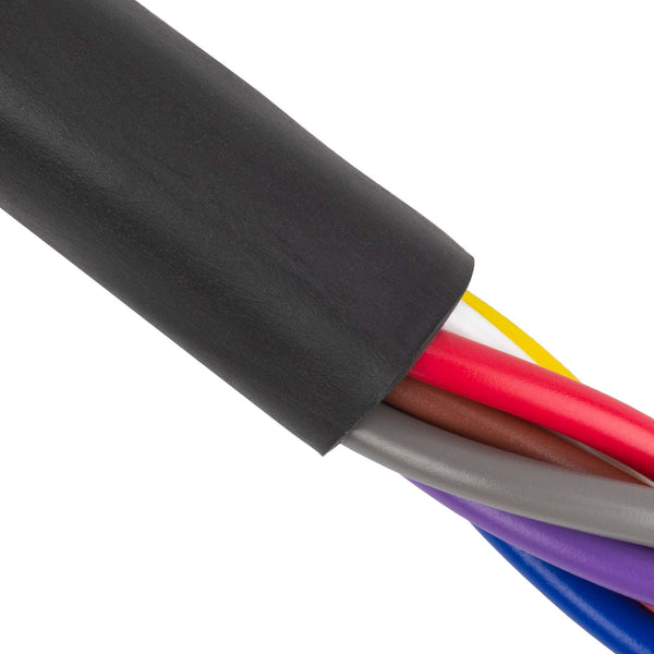
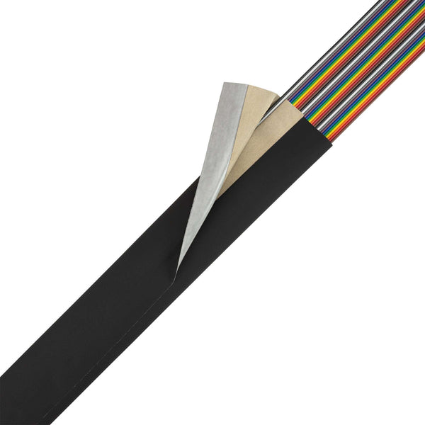
The following is a general description of how the EMI shield might be terminated given the proper hardware/tubing sizes. Since Shrink-N-Shield® tubing has a shrinkable outer jacket, it allows the installer the option of selectively shrinking the material to create a boot area near the connector which may not be fully shrunk.
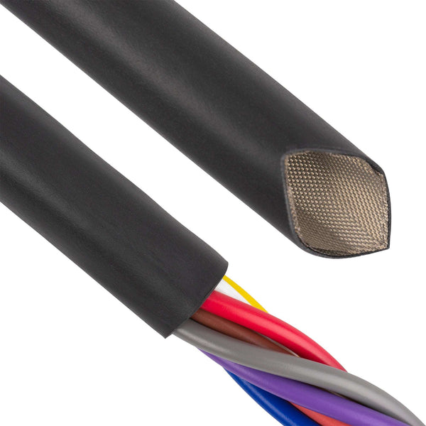
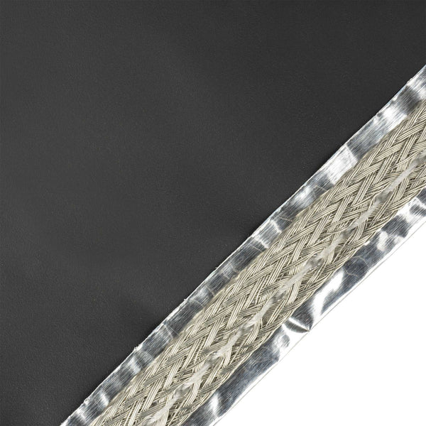
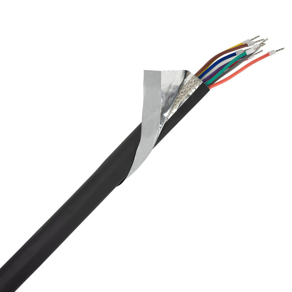
The below example illustrates an area of un-recovered tubing which will not be exposed to heating, so it is possible to trim the polyolefin tubing away, and or fold the shield fabric back over the un-shrunk tubing exposing the conductive fabric below and on top of the shrink tube. Once the fabric is exposed, it can be placed onto a standard EMI shielded connector compression cone and sandwiched under the compression ring. Once the connector has been assembled, the remaining tubing can be shrunk on the cable.

The below example illustrates a slightly different approach when the connector backshell hardware is a saddle clamp. The shield fabric is folded back over the tubing after the Shrink-n-Shield® jacket has been trimmed back allowing the conductive fabric to make contact with the saddle clamp. Careful attention to trimming the shrink-tubing is required to create a clean cut with no snags. Shrinking the tubing from the cable end towards the connector saddle clamp will help ensure that the outer jacket of the Shrink-N-Shield® tubing does not split when the end near the saddle clamp is shrunk. Once all the tubing has been shrunk the saddle clamp hardware can be assembled.

Shield Splicing
Although splicing of any EMI shield is undesirable, real world applications commonly force the installer to create them. A properly made EMI shield splice will perform equally to a continuous piece of shielding from an EMI and Environmental perspective. The critical factors in achieving a good EMI splice joint are as follows:
- Ensure good electrical contact between both pieces of shield material
- Provide a good mechanical joint so the spliced materials do not shift in operation
- Protect the joint from environmental degradation
Below is a step by step description and diagrams that will provide these requirements.
A: Wrap the cable bundle for a distance of 4.0 - 6.0 inches (where the splice will be made) using Zippertubing’s “Z-3250 Tape.” Use a 50% overlap of each tape wind.

B: Slide the first piece of Shrink-N-Shield® tubing over the tape wrap so the end of the shrink-tubing is centered on the tape wrap. Shrink in place using a hot-air heat gun.

C: Wrap a 2.0” width of Zippertubing’s Z-Block® (100) hot-melt tape over the end of the first shrunk piece of tubing so the end of the second piece of Shrink-n-Shield tubing will land flush with the end of the Z-Block® (100) hot-melt tape. The second piece of Shrink-N-Shield® tubing will fully cover the EMI tape wrap, extend over the shrunk tubing by a distance of one-half the EMI tape wrap length and align with end of the Z-Block® (100) tape.

D: Heat shrink the second piece of Shrink-n-Shield® tubing over the first. The Z-Block® (100) hot-melt tape will melt and flow around the circumference of the first tube bonding the two together. The “Z-Block® (100)” will also flow laterally and create a fillet of adhesive at the exposed end of the outer tube. The fillet and internal adhesive fill any gaps or irregularities between the two tubings and eliminate any pathway for the external environment to enter the EMI shield joint. The heat-shrinkable tubing combined with the hot-melt adhesive creates a structural bond that keeps the EMI shield fabric layers from losing electrical contact with each other.

Cable Breakouts
This simplest method for making an EMI shield breakout when using Shrink-N-Shield® heat-shrinkable tubing is as follows.
Use Zippertubing’s Z-3250-Tape to wrap all the breakout legs and the main branch of the cable bundle. Use a 50% overlap technique to ensure 100% shield coverage. Start the tape wrapping at any location of the breakout.The tape should extend 4.0 – 6.0 inches down each leg of the breakout and along the main branch. A narrow width tape works best for small diameter cables and you can increase the tape width as bundle diameter increases. Select the tape width that will minimize the creation of wrinkles and tape puckers. These typically occur when using a tape that is too large. You may find it necessary to back up over areas previously wrapped to achieve directional changes. It is permissible to stop a wrap with one piece of tape and start with another as long as you have several winds of overlap. The acrylic adhesive on the back of the fabric tape is electrically conductive so each layer will be in direct electrical contact with each other. The goal is to obtain 100% cable coverage in the break out area and not leave any gaps in joint area of the breakouts.

B: Install the Shrink-N-Shield® tubing over the smallest diameter breakout legs first. Locate the tubing as far up into the breakout intersection as possible. Heat the tubing and fully shrink in place. Wrap the last 2.0” of each breakout leg with Zippertubing’s Z-Block® (100) hot-melt tape. Slide the larger tubing over the smaller leg ends so it covers all of the Z-Block® (100) hot-melt adhesive. Shrink the larger tubing so the Z-Block® (100) is fully melted and creates an adhesive fillet in the intersection of the breakout.
When properly assembled the Z-Block® (100) will create a fully bonded breakout joint and the adhesive will have filled all the irregular gaps and voids of the breakout. The fillet and internal adhesive eliminates any pathway for the external environment to enter the EMI shield joint. The heat-shrinkable tubing combined with the hot-melt adhesive creates a structural bond that keeps the EMI shield fabric layers from losing electrical contact with each other.
Note: A mechanical cable tie or clamp can be added to the joint if deemed necessary.